There are meters that are able to take different measurements in an electrical circuit. These are:
Ammeter - for measuring current
Voltmeter - for measuring voltage (potential difference)
Ohm meter - for measuring resistance
Power meter - for measuring power
On circuit diagrams you will see meters drawn like this


Multimeters are versatile devices that allow you to carry out many different electrical measurements.
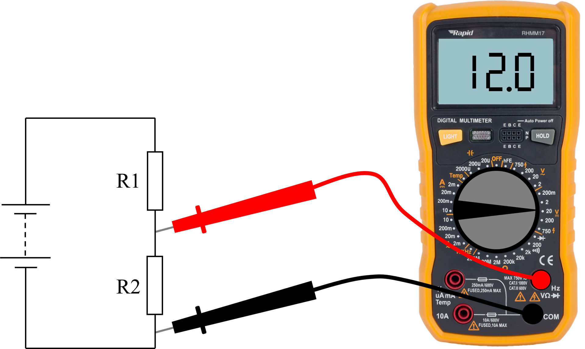
A multimeter has different scales to improve the accuracy of a measurement. For example, the 2V scale will provide two decimal places of accuracy but the 20V scale will only provide one.
If you don't know the range you will be measuring, it is good practice to start on the highest scale and work your way down to avoid damaging the meter.
As well as making sure you have the selector switch in the correct position it is sometimes necessary to move the red probe into different sockets depending on the measurement to be taken.


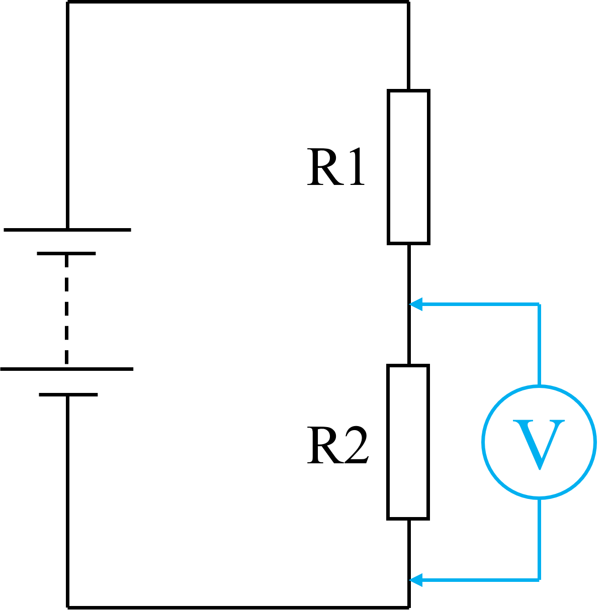
To measure voltages the meter probes should be connected in parallel with the component being tested. When measuring a voltage "dropped across" a resistor this is called the potential difference.


A voltmeter is connected in parallel with a battery or power supply to measure its voltage.


A ammeter is connected in series with the circuit that we are measiring the current of. Connecting in parallel will cause damage to the meter or for the internal fuse to blow.


When measuring resistance the power supply must be disconnected. An Ohmeter passes a small current through the resistor, measures the current and then calculates the resistance from this.


Because power is equal to voltage multiplied by current, a power meter needs to be able to measure voltage and current simulataneously. A power meter therefore has three terminals to be connected to a circuit. The W means Watts.

Power meters are used in the home to measure how much electricity you are using. A domestic electricity meter is on the top left of the photograph.

This diagram shows how multiple voltmeters and ammeters can be connected to a simple circuit.

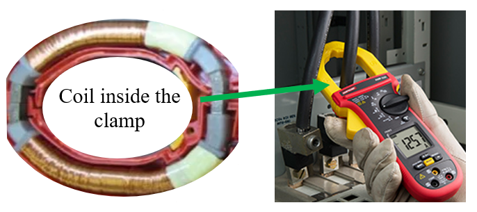
A clamp ammeter allows us to measure the current flowing through a cable without the need to break the circuit. The clamp ammeter works on the transformer principles: The clamp contains coils of wire which act as the secondary of a transformer when it is placed around a cable which forms the primary. Electronics within the meter convert the current induced into its coil into a reading on an LCD display.

