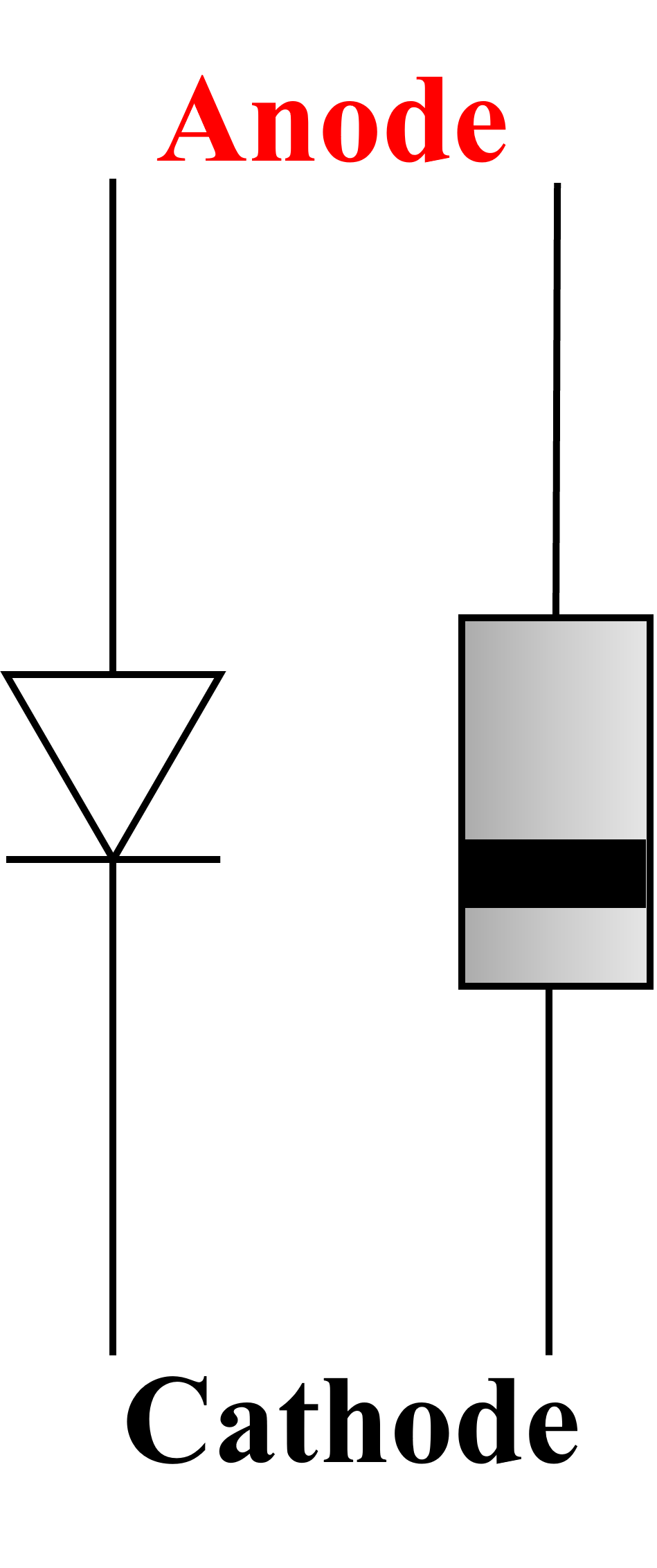
A diode is an electronic component that only allows a current to flow in one direction: from the anode to the cathode. Anode and cathode are old fashioned words for positive and negative. There are many different types of diode, each with a particular purpose. Light Emitting Diodes (LEDs) for example, are a special type of diode that produces light.
When a diode is forward biased electricity will flow through it. When it is reverese biased electricity is unable to flow through it. They are used to ensure that current only flows in the direction you require. They are used to rectify voltages (make AC into DC), prevent back EMF in relays and to protect circuits.

Diode circuit symbol (left).

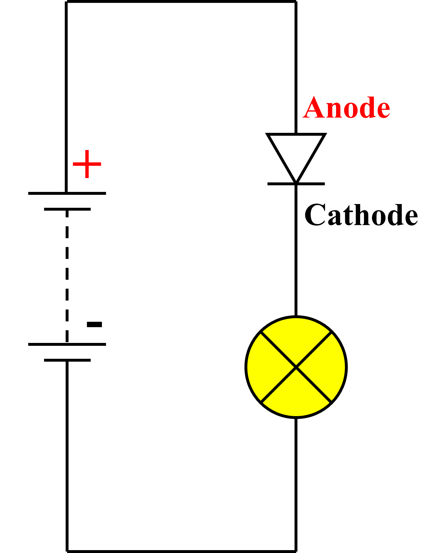
A forward biased diode: current flows from the anode to the cathode allowing the lamp to light.

A reverse biased diode: current is unable to flow through the diode because its cathode is positive with respect to the anode. The lamp does not light.
A rectifier is an electronic circuit that converts an alternating current into a direct current (AC to DC). Alternating current flows in one direction and then the opposite 50 times per second (50 Hertz) in the UK and other European countries.
Almost every single piece of electronic equipment in the home needs a DC supply. The electricity that is available from your house sockets is AC however. Mobile phone chargers contain rectifiers, TVs, consoles, you name it.
The image on the right shows the input and output voltages of the rectifier. Although the output looks like AC, it is infact DC because there is only ever a positive voltage. A capacitor can be added to the output of the rectifier however to smooth out the ripples and produce pure DC just like what is supplied by a battery.
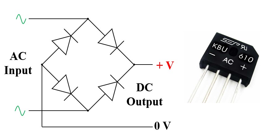
A bridge rectifier and symbol.

The animation below shows how a full-wave bridge rectifier functions. Here you can see how the four diodes direct the current in such a way that the output voltage is always positive.

The animation below shows the result of adding a capacitor in parallel with the load resistor. The capacitor acts as a reservoir, storing electricity as the input voltage rises and releasing it as the output from the rectifier drops. The output voltage graph is exagerated to demonstrate how there will still be some ripple on the output, but in a well designed circuit this would not be visible on an oscilloscope.

A thyristor or silicon controlled rectifier (SCR) is similar to a diode in that it allows current to flow in only one direction. Thyristors have an additional terminal called a gate, which is used as a method of control.
They are used as a type of electronic switch.
When no current is applied to the gate terminal no current can flow between the anode and cathode, even if it is forward biased (ie anode connected to positive, and cathode connected to negative).

Once a small electric current flows into the gate however, the thyristor starts to act as a normal diode. Even when the gate current is removed again, the thyristor will continue to act as a diode and is said to be latched.
The only was of unlatching the thyristor and make it turn off again is to remove the supply.
The circuit below show how a thyristor can be used to latch a lamp on by pressing a push to make switch.

Because no current is flowing into the gate, the thristor is switched off.

Closing the switch causes a small amount of current to flow into the gate terminal. This makes it switch on.

When the switch is opened again, no current flows into the gate terminal. The thyristor continues tro conduct because it is latched on.
The thyristor will only reset once the voltage applied to its anode drops past a specific voltage.
