Engineering & Technology
WWW.CLARVIS.CO.UK
WWW.CLARVIS.CO.UK
Operational amplifiers are extremely versatile devices. An op-amp (as it is also called) is a differential amplifier, this means it amplifies the voltage difference between its two inputs and produces an output.
They can be used as amplifiers, filters and comparators. This page is all about how they can be used as comparators.

Before we go any further, it is important to note that an operational amplifier has two supply voltages.
One positive and one negative. This is so it can amplify both positive and negative voltages. The two diagrams here show how batteries can be made to produce a positive and negative supply.
Some op-amps do not require a dual power supply. This just means that the output voltage can only be between 0 V and whatever the supply voltage is.

This diagram shows the normal arrangement where a positive supply is available.

By connecting the batteries in series and considering the link between them to be 0 Volts, postivie and negative voltages are available with respect to this point
Op-Amps can be used to compare the voltages on its two inputs and produce an output depending upon their respective voltages.
One input is called the non-inverting input, and is the one with the minus symbol.
The other input is called the inverting input, and is the one with the plus symbol.
When the inverting input is greater than the non-inverting input then the output is negative.
When the non-inverting input is greater that the inverting input then the output is positive.

The table below shows a number of different input conditions and the expected output if the op-amp is powered by a 9V supply voltage. Where the two input voltages are the same, the output would technically be zero. However it is likely that one input will always be slightly greater than the other one, even if only by 0.00001 of a volt for example
| Inverting input voltage | Non-inverting input voltage | Output voltage |
| 5 V | 0 V | -9 V |
| 0 V | 5 V | +9 V |
| 0 V | 0 V | 0 V (in theory) |
| 1 V | 2 V | +9 V |
| 2 V | 1 V | -9 V |
| -4 V | -5 V | +9 V |
| -5 V | -4 V | -9 V |
| 3 V | -3 V | -9 V |
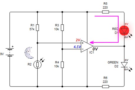
The circuit shown here demonstrates how a comparator can be used to measure light levels and light up either a red or green LED.

Just a quick note: On the diagrams the sun and the moon should be swapped over on the diagrams. Oops.
When it is dark the LDR has a high resistance and therefore a higher voltage dropped across it. The comparator compares this voltage with the 4.5 V that is supplied by the potential divider made up of R3 and R4.
Because the non-inverting input has a higher voltage than the inverting input the output switches to 9 V. This causes current to flow through the green LED.

When it is light the resistance of the LDR is lower than when it is dark. Because of this the voltage applied to the non-inverting amplifier is lower than the 4.5 V that is on the inverting input. The output of the comparator switches to 0V (it can't go negative because there isn't a -9 V supply in this case.