Individual transistors can be used to drive higher power output components such as motors and lamps.
Some times it is necessary to drive a number of outputs at a time. Instead of using many transistors, integrated circuits are available that contain a number of transistors. These are called darlington arrays and two such components are the ULN2803 and ULN2003.
An advantage of transistor arrays is that it allows much smaller circuit board to be designed since a single chip takes up less space on a PCB than a number of separate transistors.
Each darlington transistor in the ULN2803 is able to operate at a maximum of 50 V and deliver a current of 500 mA. The inputs can only accept a maximum of 30 V though.
The ULN2003 is identical to the ULN2803 but with only seven outputs.
The diodes in the ICs are there to prevent back EMF damaging the transistors when inductive loads such as motors are connected.


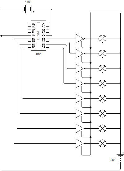
The PIC chip needs a voltage of 4.5V to work but the use of the ULN2803 and a separate 24V battery allows the microcontroller to control high power 24V lamps.
The circuit diagram doesn’t show it but the Gnd pin must be connected to the 0V rail of the power supplies (the negative terminals of both batteries).
This IC allows motors to be switched on and off from a low power circuit such as a PIC chip.
What is most important is that it also allows the direction of a motor to be controlled. It is therefore a great chip for building robots and other moving products.
The L293 has two enable inputs which can be used to deactivate the outputs of the drivers when required. These are digital inputs and can therefore be either a logic 1 or a logic 0 (high or low).
The L293D has the advantage that the outputs can supply voltages of up to 36V (a PIC can only manage 4.5V) and each output can supply a current of up to 600mA which is much greater than a PIC or similar circuit can cope with.
As well as controlling DC motors, the L293D is also used for controlling stepper motors.

A heatsink can be fitted to allow the heat generated by the IC to be given off. This helps to prevent overheating.


Power Supplies
The Vss pin is the low voltage power input which should be connected to the same power supply as a microcontroller or other circuit which is connected to the inputs of the L293D. This can be a maximum of 7V.
The Vs pin is the higher voltage power input and can be between 4.5V and 36V.
The Gnd pins are the 0V connections and should be connected to the 0V rail that is shared with the input circuit. There are four because the pins are used to help dissipate the excess heat generated by the chip.
The L293D heats up when it is in use which can be damagd if it becomes too hot. This can be prevented by connecting a heatsink to it. The cheapest way is to include a large area of copper on your PCB connected to the Gnd pins to spread the heat away from the chip. Another method is to attach a metal heatsink to the top of the chip.
