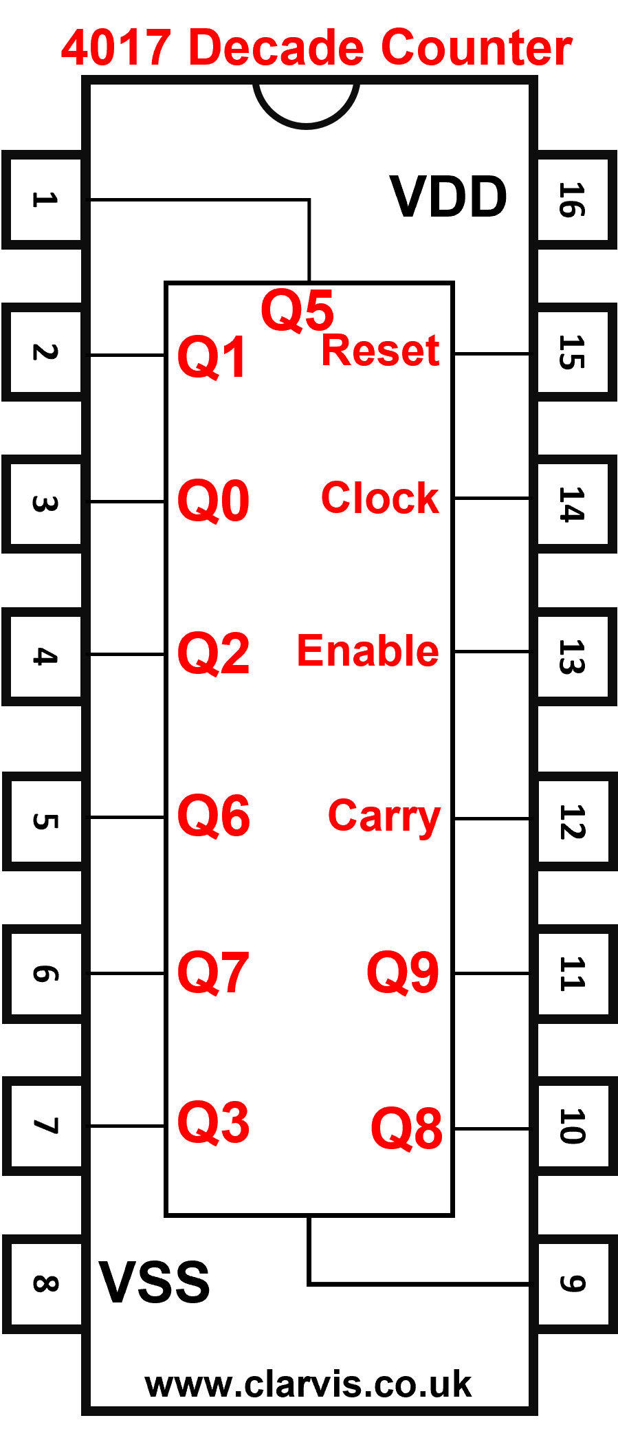
A 4017 integrated circuit has many uses but for us it is useful because it allows LEDs to light up in sequence. A 4017 counter lights up each LED in turn, every time a pulse is applied to the clock input.
The RESET input (R) makes the counter go back to 0 when it is a logic 1.
The CLOCK input (>) makes the count up to the next number when a logic 1 pulse is received.
The ENABLE input (EN) only allows the 4017 to count when this is logic 0.
VDD is the positive supply
VSS is the 0V supply


This circuit counts every time the count switch is pressed.
The reset and clock inputs are normally low because they are connected to the 0V rail via resistors R1 and R2. When a switch is pressed a direct connection is made between the input and +V therefore forcing it high. Every time SW1 is pressed the next LED is lit. Once the 9th LED is lit it starts from the first one again.
This circuit suffers from switch bounce, which means that more than one count may occur due to the vibration of the switch contact when it is pressed. See switch debounce.
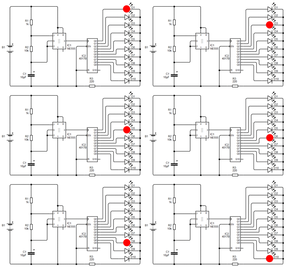
This circuit uses a 555 timer configured as an astable multivibrator. The counter will count from 0 to 9 automatically.

A 7-Segment display is made up of seven rectangular LEDs arranged in a figure of 8 pattern. By lighting up the LEDs in the right order it is possible to get them to display the numbers 0 to 9.
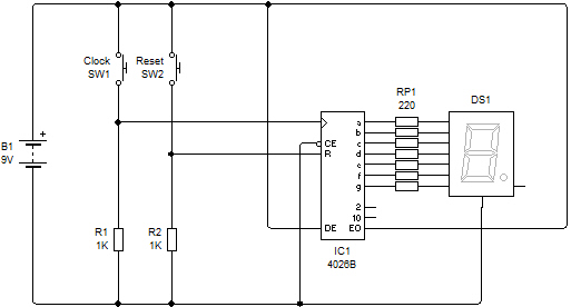
An integrated circuit (IC) is available called a 4026 which allows you to build a counter that will increase its value every time it receives a clock pulse.
This pulse could come from a switch of some kind or the output of an other circuit, like an astable circuit for example.
What each pin on the chip does
CE = Chip Enable: This must be connected to 0V to turn the 4026 on.
DE = Device Enable: This must be connected to +V to turn the 4026 on.
EO = Enable Output: This must be connected to +V to turn on the LED display.
R = Reset: When this input has a logic 1 connected the display will be reset.
> = Clock Input: Each time a logic pulse is received by this input the display will increase its value by 1.
a, b, c, d, e, f, g = LED outputs: Each LED segment is connected up to the each of these outputs. The 220R resistors must be included to limit the current flowing through the LEDs, this prevents them from becoming damaged.
VDD is the positive supply and VSS is 0V.


