Logic gates are circuits with one output and one or more inputs. They are used to make decisions
based on the state of their inputs. Unlike analogue circuits, such as audio amplifiers, a logic circuit only
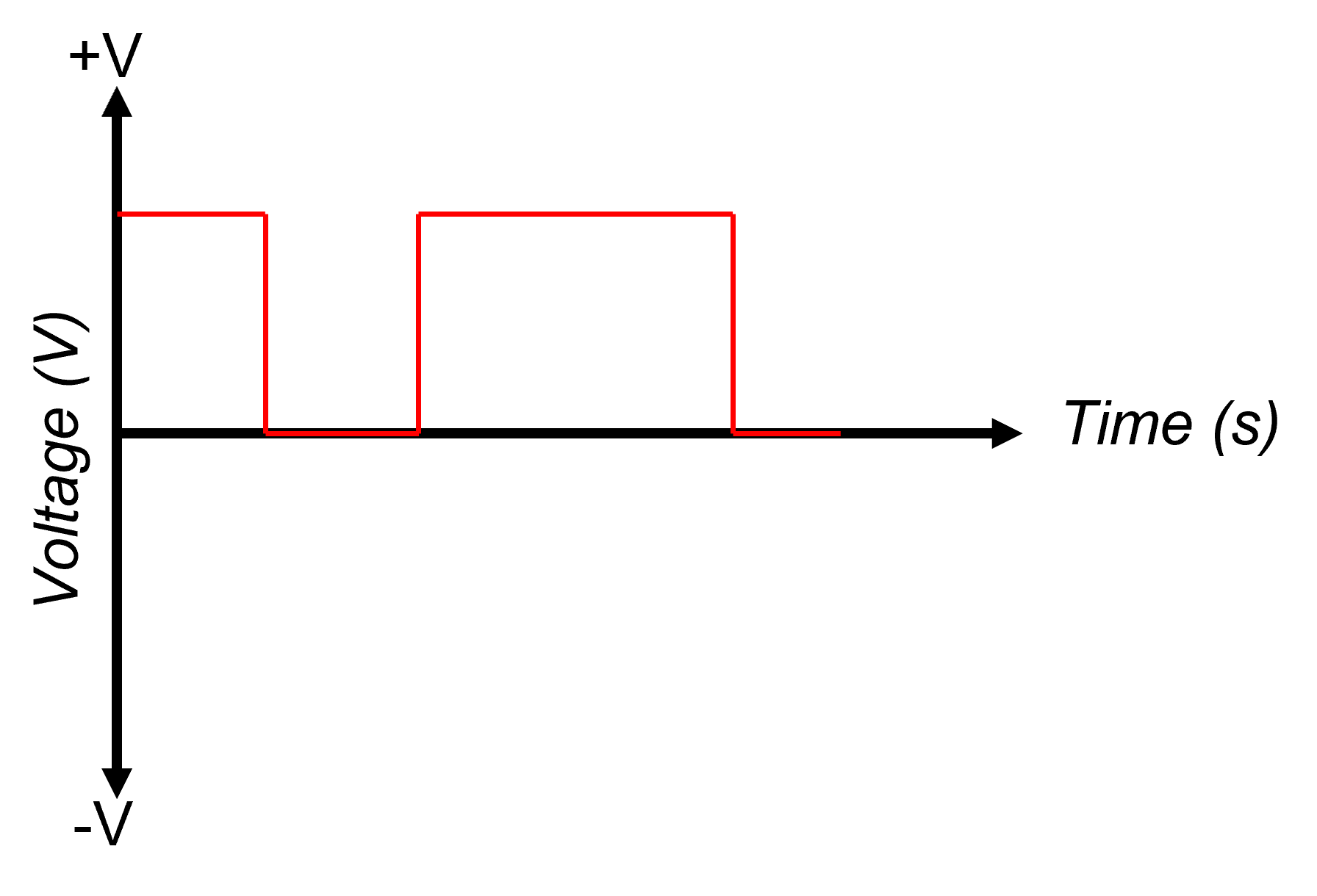
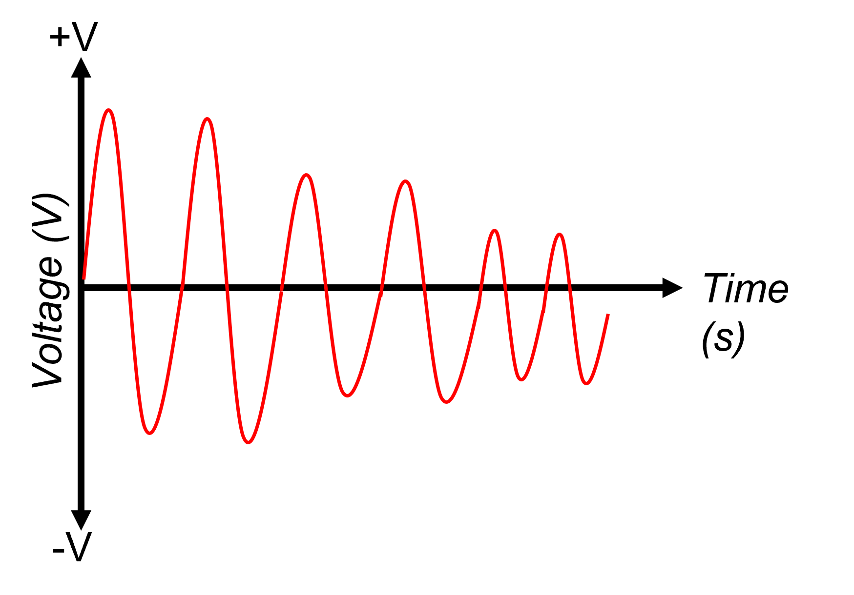
has two states, either on or off. The differences between an analogue and digital signals can be seen below. The voltage of an analogue signal can vary between any voltage without any distinct boundaries. The digital signal however
only has two states: on and off.
In digital electronics these terms are often used interchangeably:
On = high = logic 1
Off = low = logic 0
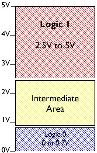
In Electronics logic levels are usually represented as different voltages. Depending on the technology used, the threshold voltages for particular logic levels vary. Two common technologies are TTL and CMOS, the logic thresholds are shown below. Note how the logic voltages are fixed in TTL circuits but in CMOS circuits the voltage levels are a percentage of the supply voltage. This allows CMOS circuits to be less succeptible to electrical noise.

A buffer is a logic gate where the output state is the same as the input state.


The output of a NOT gate is the complement (opposite) of its input.


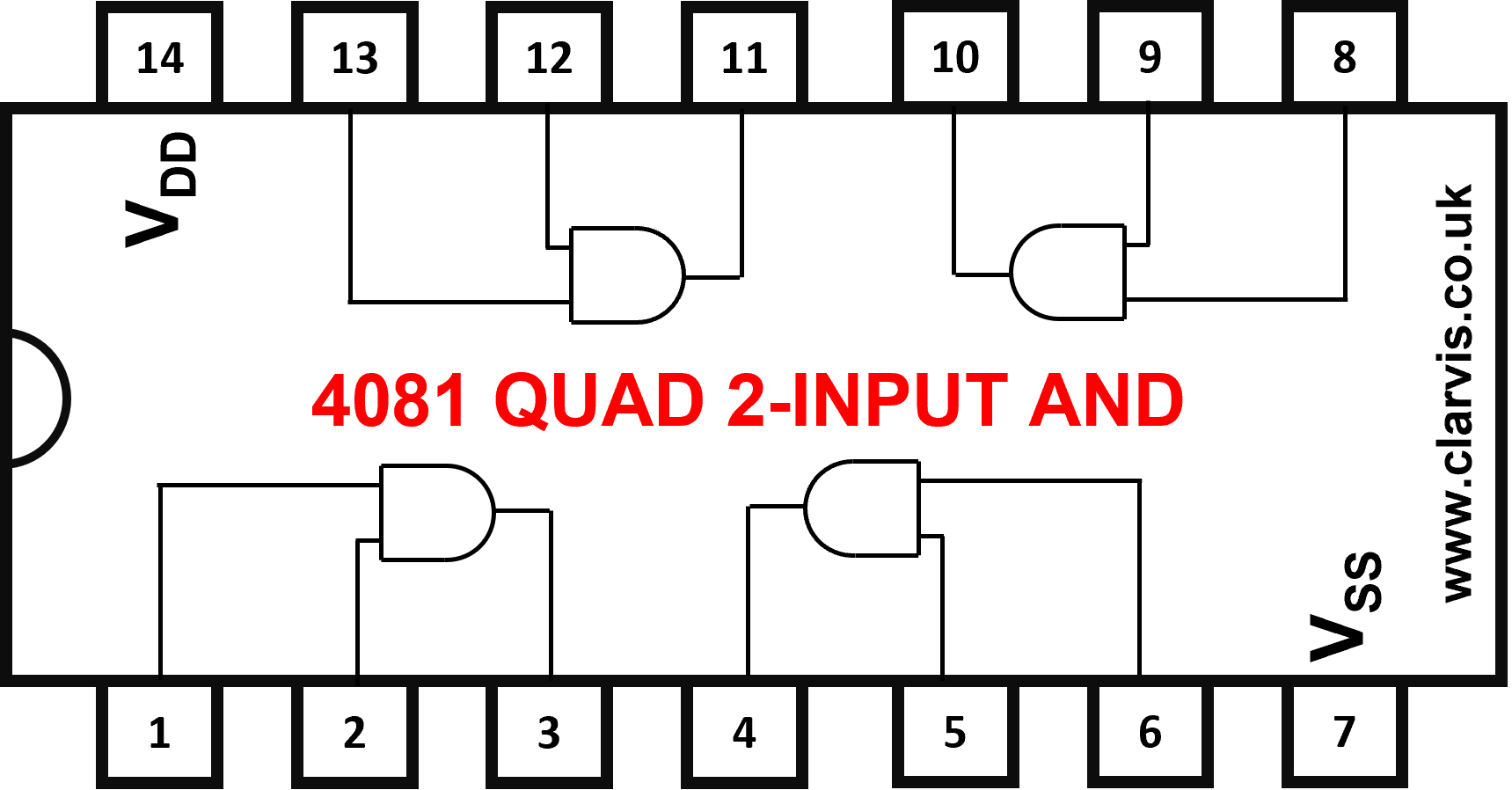
For the output to be high all inputs must be high, otherwise the output is low. The diagrams shown are for a 2-input AND gate but AND gates can have many inputs.


For the output to be low both inputs must be high, otherwise the output is high. Imagine an AND gate with a NOT gate connected to its output.


For the output to be be high either or both of the inputs must be high, otherwise the output is low.

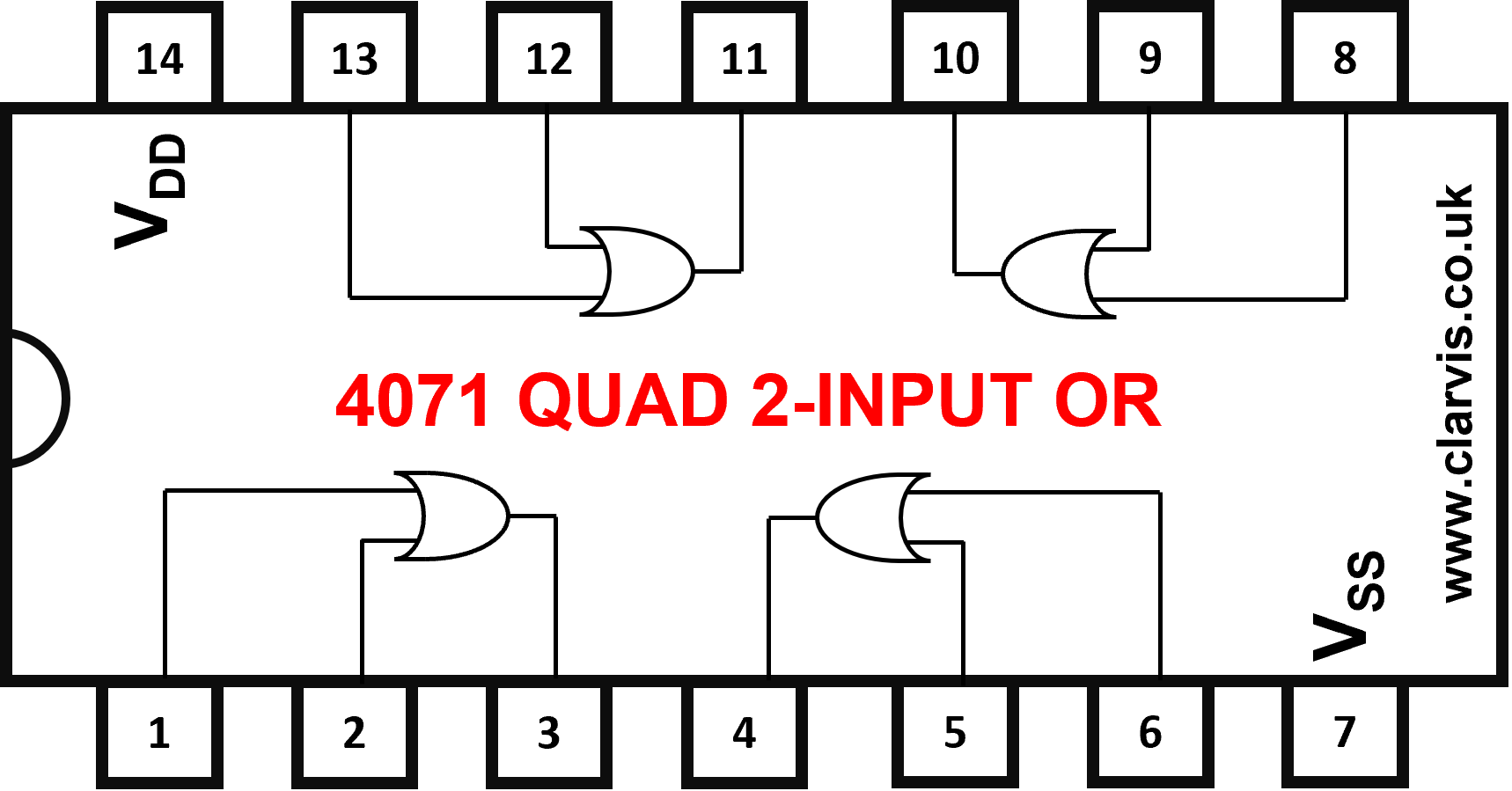
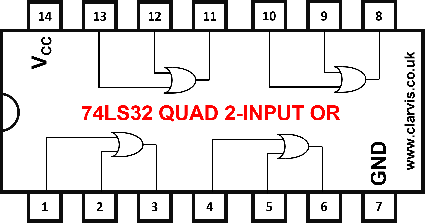
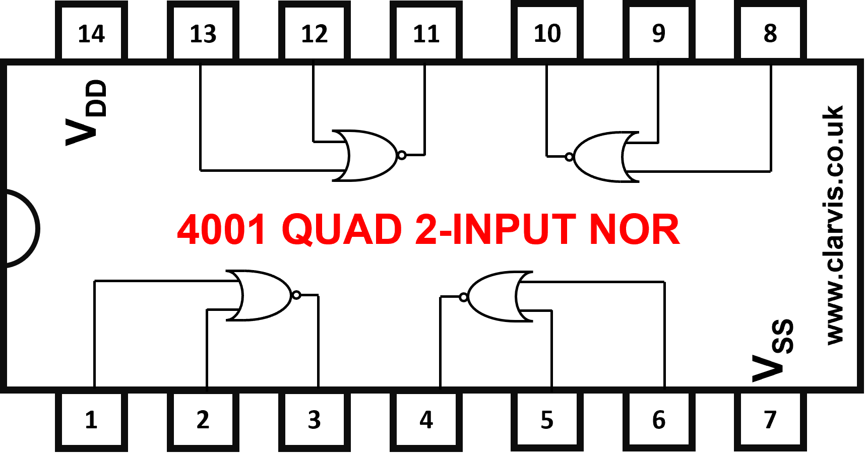
For the output to be be low either or both of the inputs must be high, otherwise the output is high.


For the output to be high either input must be high but both must be not.


For the output to be low either input must be high but both must be not. XNOR gates are not commonly used.

