A transformer is an AC electrical device that is used to convert voltages. It relies on the principle of mutual induction .
A basic transformer consists of two coils of enameled copper wire wound around an iron core. One coil is called the primary and the other the secondary.
The electrical power is supplied to the primary winding and the output is taken from the secondary winding.
The ratio of the number of turns of wire on the primary and secondary windings determines the relationship between them. There are three main types:
Step-up transformer: The secondary voltage is greater than the primary voltage.
Step-down transformer: The secondary voltage is smaller than the primary voltage.
I
solation transformer: The secondary voltage is the same as the primary voltage.
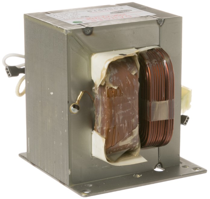
Microwave oven step-up transformer

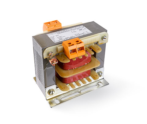
Mains step-down transformer

Isolation transformer

Distribution transformer


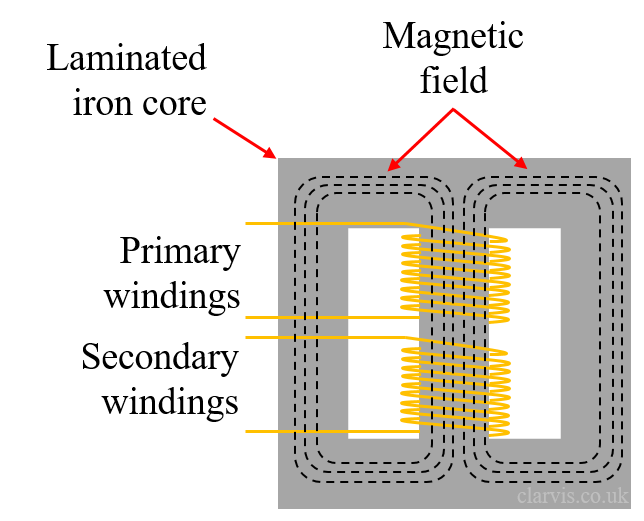
When an alternating current flows into the primary windings an alternating magnetic field (Φ) is generated in the iron core. This is called induction. When an alternating magnetic 'cuts' or crosses the second set of windings an electric current is induced into the secondary windings. This process is called mutual induction.
Electricity - - -> Magnetism - - -> Electricity
It's important to note that there is no electrical connection between the primary and secondary windings, only a magnetic coupling.

The diagram shows a transformer with its primary connected to an AC supply and the secondary connected to a load, in this case a resistor.
Current flowing through the primary windings causes a current to flow through the secondary windings. The amount of primary current is dependent on the secondary current caused by the load.
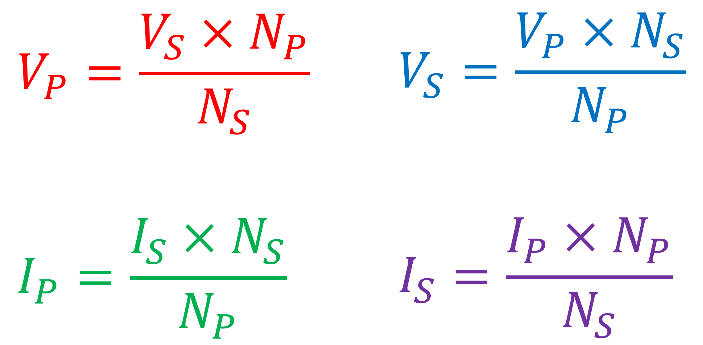
VP = Primary voltage
IP = Primary current
NP = Number of turns of wire on the primary
VS = Secondary voltage
IS = Secondary current
NS = Number of turns on the secondary.
The relationship between the number of turns, primary voltage and current and secondary voltage and current are explained with this formula:

Here are some useful transpositions

Looking at the example below, the unknown values can be calculated using the formulae shown:


This demonstrates that due to the ratio of turns:
The secondary voltage is ten times smaller than the primary voltage
The secondary current is ten times greater than the primary current
Two forms that transformer cores can take are the core type and the shell type. Modern mains transformers are of the shell type because they are more efficient.


The diagram shown is of an isolation transformer which is used to provide a safer electricity supply to equipment in hazardous areas. This could be on a building site where there can be water and risk of physical damage to equipment.
Reducing the voltage to 110V first of all reduces the risk of electrocution since this is half that of the mains supply. Half the voltage, half the current if you come into contact with the live.
There is an additional "tap" in the mid point of the secondary which is connected to earth. This means that should you come into contact with either of the secondary output terminals it will only be at a potential of 55V. This voltage is much less likely to cause harm.

All electrical equipment has inherent inefficiencies and transformers are no exception. This page explains the different mechanisms that cause a transformer to lose energy.
Because the core itself is electrically conductive, the changing magnetic field introduced by the windings cause a current to be induced into the core. This current circulates within the core, producing heat and wasting energy. To reduce this effect transformer cores are normally laminated, consisting of many thin metal sheets insulated from adjacent sheets with varnish. This minimises eddy currents to within a small area.

The core of the transformer is constantly being magnetised and demagnetised by the magnetic field induced into it by the current flowing through the windings. This takes energy since once the core is magnetised it takes an effort to demagnertise it and change magnetic polarity. This is called hysteresis loss .
The primary and secondary windings are made of copper wire and, like all conductors have resistance. Because of this, as the current flows through the wires heat is produced according to the power formula:

Therefore, the higher the resistance of the windings, the more power is wasted as heat. Because of this, copper losses are sometimes referred to as resistive losses.
Ideally we want all of the magnetic flux to be contained within the core of the transformer but some escapes into the surrounding area. This loss of flux reduces efficiency.
